


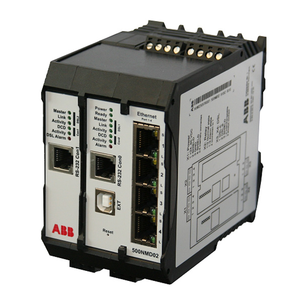
500NMD02
DIN rail integrated managed switch 560NMD02
- 4x fast Ethernet 10/100 baseT port(RJ45, electrical, autonegotiating)
- 2x SDSL-port up to 11.4 Mbps
- 2x RS232 interface for configuration or tunneling of serial data
- EXT connector for external storage of configuration data
- STP and RSTP support
- Alarm relay configured by software
- Functionally compatible with 560NMS24
- 35 mm DIN-rail mountable
- 24-60 V DC supply voltage
Product Detail
The DIN rail mountable 560NMD02 is a managed plug and play layer-2-switch providing 4 fast Ethernet auto-negotiating RJ45-ports with auto MDI/X (Automatic Crossover Detection and Correction) and two 2-wire SDSL-ports for use with private copper cables. The switch is intended for distributing Ethernet within a station through the RJ45-ports.
The SDSL-ports can be used for interconnecting stations with a maximum distance of 20 km (copper cable with diameter of 0.8mm). The switch is able to provide redundant topologies by the (Rapid) Spanning Tree Protocol in one device. The modem can be connected to 560NMS24 and 560NMS34.
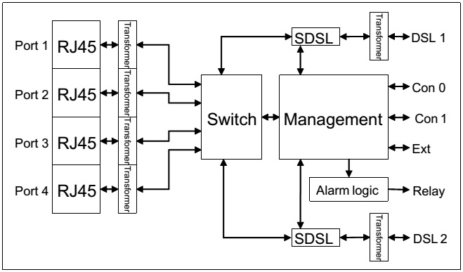
Figure 1: Block diagram of 500NMD02
For documentation purposes, the Ethernet ports are labeled from 1 to 4. The SDSL ports are connected through a pluggable screw connector. There is no specific uplink port. All ports are equal in function. Link and speed status of each Ethernet and SDSL port are displayed by status indicators (refer to Connectors and Indicators).
The switch learns Ethernet addresses by analyzing received frames and stores them in a lookup-table (max. 2048 entries), which is used to forward frames only to the correct port. If it is a broad- or multicast address or if the target address is not found in the lookup-table, a received frame is forwarded to all ports except the receiving one. If an entry in the lookup-table is not refreshed by an incoming frame with the specific source address, it is aged out within a maximum of 304 seconds (by default, value is configurable).
Regarding IEEE 802.1Q VLAN frames, the switch can be configured to VLAN or transparent mode. In transparent mode the switch will never change any frame or TAG of a frame; in VLAN mode it can be configured to support several applications like trunk or access ports.
Quality-of-Service is supported by the switch if an IEEE 802.1p compliant frame format is used. The switch can separate frames into up to four queues, which can be configured to priority based or weighted-fair queuing.
The 560NMD01 uses a wide range power supply and works with a voltage from 24 to 60 V.
The component itself, the Ethernet ports, the SDSL connections, the RS232 interfaces and the extension bus interface (Ext) are hot-plug capable.
The 500NMD02 switch consists of four equal RJ45 Ethernet ports, two SDSL transceivers and two RS232 interfaces for configuration and tunneling of serial data. Each RJ45 port can be connected to a Cat. 3 (for 10 Mbps) or Cat. 5 (for 100 Mbps) Ethernet cable with a maximum length of 100 meters. The cable should only be used for in-house connections. Since Auto MDI/X is supported by the 500NMD02 switch for the RJ45 ports, there
is no need for crossover cables.
The SDSL interfaces can be connected to 2-wire customer-owned copper lines. The maximum bridgeable distance is 20 km for 0.8 diameter copper cable with a transmission rate of 192 kbps. Depending on the distance, the transmission rate can be configured to up to 11 Mbps.
The status of the interfaces can be monitored by two LED indicators. For the Ethernet ports these are located at each above and below RJ45 jack.
Ethernet (RJ45)
A green Link LED (labeled L) indicates an active Ethernet connection.
Activity status:
– Off – No Connection
– On – Ethernet Connection Established (Link)
– Flashing – Ethernet Activity (Transmission or Reception of
frames)
A yellow Speed LED (labeled S) indicates a 10 or 100 Mbps
connection.
Speed status:
– Off – Ethernet Speed of 10 Mbps
– On – Ethernet Speed of 100 Mbps
DSL (pluggable screw connector)
The state of the DSL interface can be monitored through the
green LEDs labeled Activity and Link.
Link status:
– Off – No DSL connection
– On – DSL link established
Activity status:
– Off – No DSL connection
– Flashing – DSL activity (Transmission or Reception of
Frames). DSL connection negotiation if Link is off
A LED labeled Master shows the operational mode (Master
or Slave) of the DSL interface.
Master status:
– Off – Mode is Master
– On – Mode is Slave
RS232 (RJ12)
The RS232 interfaces can be monitored by the LEDs DCD
and Activity.
DCD status:
– Off – DCD signal not active
– On – DCD signal active
Activity status:
– Off – No data send or received
– On – Data is being send or received
General
Two additional LEDs labeled Power and Ready determine the
state of the device itself.
Power status:
– Off – Device has no power
– On – Device power is connected
Ready status:
– Off – Device is not operational
– On – Device is operational
Detected errors are signalized by a red Error LED (labeled
Alarm) together with an Alarm condition. The alarm condition
can also be signalized by an isolated alarm relay.
The conditions that lead to an alarm state can be configured.
An extension jack labeled (Ext) allows connection additional
hardware, e.g. a portable configuration stick for external storage of configuration data.
The 500NMD02 provides a total of six ports for use with end devices, switches, bridges, hubs and routers using the DSL port. Star, ring or line topologies can easily be built by this family of switches. The typical application for this product are line and ring topologies.
Redundant topologies are automatically detected and handled by the Rapid Spanning Tree Protocol (RSTP). This is fully backward compatible with the wide-spread Spanning Tree Protocol (STP).
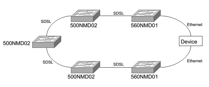
Figure 2: Typical topology for use with 500NMD02
Management and Configuration of the 500NMD02 can be done by Telnet, Secure Shell (SSH), SNMP, RS232 or Web-interface.
All methods can be used to either read or write parameters of the device. Additionally the interface and alarm state of the device can be monitored by IEC 60870-5-101 or -104.
An existing configuration can be saved as well as restored. The configuration can also be stored to an external configuration stick (560NMA01), which supports the simple exchange of a device without trained personnel.
By default, the IP address for the configuration of a 500NMD02 switch is 10.0.0.2 with a subnet mask of 255.0.0.0 and a gateway of 10.0.0.1. The SNMP strings are ‘public’ for read-only access and ‘private’ for read-write operations. Reset to default values could be done via RS232 interface, while press ‘i’ during startup process.. Connections for configuration purposes are accepted through any interface. All Ethernet ports are administratively up in default state.
The preconfiguration for the RS232 interfaces are baudrate 57600, 8 databits, no parity, 1 stopbit (57600, 8N1). The command-line interpreter for configuration via this interface can be accessed by any terminal software (e.g. Hyperterminal).
Ports
All ports of the device can be disabled or enabled by configuration. Furthermore, the speed and duplex of any port can be set according to its capabilities. This is 10 or 100 Mbps, Full or Half duplex for the Ethernet ports and 192 kbps up to 11 Mbps in steps of 8 kbps for the SDSL ports.
It is also possible to use an auto-detect setting. For the SDSL port it is recommended to set the 500NMD02 device closer to the control center to a fixed speed setting, while setting the communication partner at the RTU side to auto-detect.
Ports connected to a RTU from RTU500 series should be configured with auto detect.
The switch supports a multiple of additional features, like port mirroring, bandwidth control, or quality of service.
Alerts, Notifications and Logging
The 500NMD02 provides Syslog and SNMP capabilities to send alerts and notifications to one or more predefined destinations. There is also a relay for configurable out-of-band alerts.
For each Syslog server entry a severity can be entered to filter outgoing messages.
A system log stores critical messages. The log can be accessed by Telnet and implements a timestamp either by uptime, or date and time if a time server is configured.
For Syslog and local logging, a SNTP time server can be used to synchronize clocks and to enable the generation of date and time timestamps instead of uptime referencing messages.
Redundancy Support
The redundancy protocols Spanning Tree Protocol (STP) and Rapid Spanning Tree Protocol (RSTP) are fully supported. Without configuration RSTP is enabled for all ports. Switching from RSTP to STP is done automatically to ensure the compatibility to existing STP installations.
For every port, the (R)STP parameters can be configured separately. This includes port priority for root bridge control as well as point-to-point and edge connection settings. A global bridge priority is also settable.
Authentication
Access to the Telnet and SSH interface of the 500NMD02 is controlled by a two-level password protection. The first level enables the user to access parameters in read-only mode and has to be entered as soon as a connection is established. To read and write parameters, the device has to be put in a configuration mode that requires an additional password. Any password can be disabled. Some security sensitive information, such as the configuration file, may not be available in read-only mode.
Besides the two-level password protection, users may be authenticated by a standard RADIUS server.
Udating…………..
In addition to the RTU500 series general technical data, the following applies:
 0
0 0
0
 0
0